


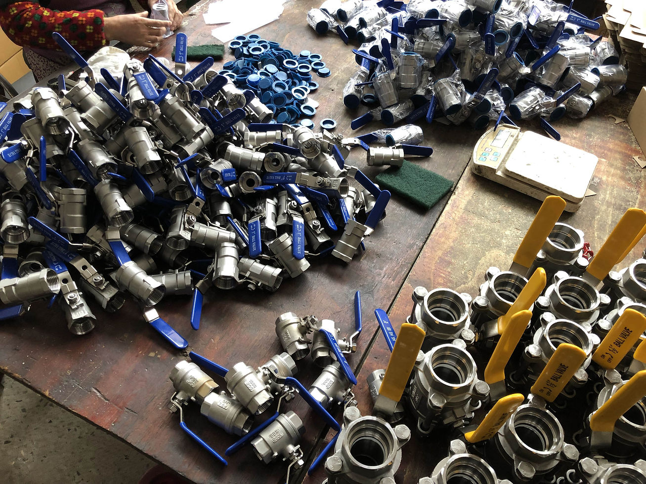
Ball Valve Cavity Pressure Relief: SPE, DPE, DBB and DIB

Ball valve cavity pressure is the pressure trapped between the upstream and downstream seats when both seats isolate the body cavity. If liquid in that closed volume warms, its thermal expansion can raise cavity pressure far above line pressure. The result may be excessive operating torque, seat damage, stem leakage, body-joint leakage, or a hazardous release when the valve is dismantled. The correct protection depends on valve design, seat directionality, process phase, required isolation philosophy, and where any relieved fluid is permitted to go.
The short answer is simple: a standard floating or trunnion ball valve should never be assumed to relieve trapped cavity pressure safely. Buyers must ask how the offered seat design behaves, in which direction it seals and relieves, and whether the valve provides self-relieving seats, a drilled ball, a body relief device, or an external equalization arrangement. That answer must be documented on the approved drawing and verified against the process hazard review.

What Creates Trapped Pressure in a Ball Valve?
A closed ball valve contains a finite body cavity around the ball. In many designs, the seats contact the ball on both sides and can isolate that cavity from the pipeline. Trapping can occur after the valve closes on liquid, after hydrostatic testing, during steam-out or hot cleaning, when solar heating raises the temperature of an outdoor valve, or when a cold liquid gradually reaches ambient temperature. Liquefied gases and volatile services can create additional vaporization concerns.
Liquids are comparatively incompressible. A small temperature increase in a completely blocked liquid volume can therefore create a large pressure increase before any visible movement occurs. The exact value depends on fluid properties, initial gas content, cavity volume, component elasticity, seat behavior, and temperature change. Because these variables are application-specific, a generic rule of thumb is not an adequate design basis.
Floating Ball Valves and Trunnion Ball Valves Behave Differently
In a floating ball valve, the ball is supported primarily by the seats and can shift slightly under differential pressure. Upstream pressure pushes the ball toward the downstream seat, supporting shutoff. Cavity-pressure behavior depends on seat geometry and preload. Some designs may allow cavity pressure to move a seat away from the ball and relieve, while others may continue to trap pressure. Similar external appearance does not prove identical behavior.
In a trunnion-mounted ball valve, the ball is mechanically supported by trunnions and the seats commonly move toward the ball. Spring force and line pressure can energize the seat. This architecture enables defined single-piston-effect or double-piston-effect behavior, but the terms must be tied to the actual valve design. Trunnion construction alone does not tell a buyer whether the cavity relieves automatically or remains isolated.
Single-Piston-Effect Seats
A single-piston-effect seat normally seals when line pressure acts from the pipeline side, while sufficiently high cavity pressure can act over an effective area that pushes the seat away from the ball. The body cavity then relieves toward the lower-pressure pipeline side. This arrangement can provide automatic cavity-pressure relief without a separate body relief valve, provided the differential forces and seat design perform as intended.
The advantage is protection against thermal overpressure. The tradeoff is that one seat may not maintain isolation against pressure coming from the cavity side. When an engineer specifies double block and bleed, the expected sealing direction and test method must be clear. The phrase double block and bleed is sometimes used loosely, so the purchase specification should describe the functional isolation requirement rather than relying on an acronym alone.
Double-Piston-Effect Seats
A double-piston-effect seat can remain energized by pressure from either the line side or the body-cavity side. This may provide an additional isolation barrier if one seat is damaged. It can be valuable in services where the operator wants both seats to continue sealing against the cavity. However, that same behavior can trap thermal expansion. A dedicated relief path is generally required when liquid can be blocked in the cavity.
Common design solutions include a body pressure-relief valve, an external piping connection to a safe system, or a combination of one self-relieving seat and one double-piston-effect seat. The relief destination matters. Discharging toxic, flammable, cryogenic, or environmentally harmful fluid directly to atmosphere may be unacceptable. Relief should be routed according to the plant's process and safety design.
DBB, DIB-1, and DIB-2: Ask for the Functional Diagram
Double block and bleed arrangements isolate two pressure sources and allow the intermediate cavity to be bled or monitored. Double isolation and bleed configurations may use seats with different pressure-response characteristics. Labels such as DBB, DIB-1, and DIB-2 are useful only when the valve manufacturer and purchaser share the same definitions and test basis.
The safest procurement practice is to request a seat schematic. It should show the upstream side, downstream side, cavity, sealing directions, pressure-energized areas, relief direction, bleed connection, and any relief device. The data sheet should also state the normal valve orientation if the design is directional. This single drawing prevents many misunderstandings during technical bid evaluation.
Other Cavity-Relief Methods
A small pressure-equalizing hole can be drilled through the ball or seat area in selected applications. This prevents the cavity from being isolated when the valve is in the specified position. The solution is simple, but it makes the valve directional and can compromise bidirectional isolation. Orientation marking and installation control become essential. A drilled ball should never be added as an informal field modification without engineering approval.
An external bypass can equalize pressure around a large valve before operation and reduce opening torque. It may also support warming, filling, or pressure balancing. A body relief valve protects against overpressure but introduces its own set pressure, capacity, materials, discharge routing, isolation, maintenance, and testing requirements. Each accessory becomes part of the pressure-protection system and must be included in documentation and commissioning.
How to Specify Cavity-Pressure Protection
Give the manufacturer the fluid, phase, composition, design pressure, normal pressure, design and operating temperatures, minimum temperature, heating scenario, valve size, class, orientation, seat materials, required flow direction, isolation function, and acceptable relief destination. Identify whether the cavity can contain liquid after pressure testing, flushing, cleaning, or normal operation. Describe any blocked-in scenario considered by the process design.
Then require a written response covering seat effect, sealing direction, automatic relief direction, minimum differential needed for relief, body-cavity pressure limit, relief-device details, and any orientation marking. For critical service, include the arrangement in the valve data sheet, general arrangement drawing, bill of materials, inspection and test plan, operating manual, and spare-parts list.
Testing and Factory Verification
Standard shell and seat tests verify pressure-boundary integrity and closure leakage under defined conditions, but they may not demonstrate the full thermal-relief behavior of a special seat system. The inspection plan should identify any additional functional tests needed to confirm seat directionality, cavity pressure relief, body bleed operation, or relief-device set pressure. Acceptance criteria must be agreed before manufacture.
Test records should identify the valve serial number, orientation, pressure source, seat under test, cavity pressure, test medium, duration, result, and calibrated equipment. If the design relies on an external relief valve, verify its certification and set pressure separately. After wet testing, drain and dry cavities when residual water could corrode, freeze, contaminate, or create a later pressure hazard.
Operation and Maintenance
Operators should treat the body cavity as potentially pressurized even after both sides of the pipeline are depressurized. Before removing a drain plug, body connector, stem packing, or actuator, follow the approved isolation and depressurization procedure. Use the bleed point to verify zero energy, recognizing that a blocked bleed port can give a false indication. Personal protective equipment and safe discharge routing remain necessary.
Maintenance should inspect seats, body seals, bleed fittings, relief valves, external tubing, and orientation markings. A rising frequency of cavity-pressure alarms or body-bleed releases may indicate seat damage, temperature excursions, incorrect valve alignment, or process migration. Replacement seats must preserve the original pressure-response design; substituting a similar-looking seat can change the isolation and relief function.
Procurement Checklist
A complete inquiry should state valve construction; bore; body, ball, stem, seat, and seal materials; seat-effect arrangement; sealing directions; DBB or DIB function; cavity relief method; relief destination; drain and vent connections; orientation; pressure-temperature rating; testing; marking; documents; and spare parts. Ask suppliers to identify deviations explicitly and to provide the functional seat diagram with the quotation.
During bid comparison, reject answers that merely say self-relieving without explaining direction and conditions. Confirm whether the proposed arrangement protects every operating scenario identified by the process engineer. Check that actuator torque calculations include the maximum differential pressure and possible seat loading. Finally, verify that the installation drawing and operating procedure match the approved valve orientation.
Frequently Asked Questions
Can every ball valve relieve thermal expansion automatically? No. Relief depends on seat geometry, preload, effective pressure areas, valve construction, and the direction of differential pressure. Obtain a design-specific statement from the manufacturer.
What is a self-relieving ball valve seat? It is a seat designed so that excessive body-cavity pressure can overcome the seat force and relieve toward a lower-pressure pipeline side under defined conditions.
Does double-piston effect provide better isolation? It can provide an additional sealing barrier against cavity pressure, but it may also trap thermal expansion. Better depends on the required isolation and relief philosophy.
Is a body bleed valve the same as a relief valve? No. A bleed valve is normally operated to drain, vent, or verify isolation. A pressure-relief device opens automatically at a defined condition and must discharge safely.
Why can a valve be hard to operate after heating? Trapped liquid expansion can increase cavity pressure and seat load, raising torque. Other causes include deposits, corrosion, actuator problems, or unsuitable seat materials, so diagnosis is required.
Final Answer
Ball valve cavity-pressure protection is a design function, not a catalog checkbox. The buyer must understand what becomes trapped, how each seat responds to pressure from both directions, and where excess pressure can safely go. A documented seat schematic, defined test plan, controlled orientation, and safe operating procedure turn the concept into verifiable protection. Wenzhou Wofer Valve supports global buyers with ball-valve configuration review, seat-arrangement clarification, manufacturing inspection, pressure testing, and export documentation based on project requirements.


Comments